More on Ballasting

I’ve finished my series about ballasting at the Scratchbuilder’s Guild. Have a look at it with this link and let me know what you think.

ballast-step-15.jpg

The next step will be the grass, bushes, and other scenic details. Once these are done things should blend together and look a whole lot better.

Later!

Scott

Ballasting at the Scratchbuilder’s Guild

Well folks, Ron Pare invited me to be a contributing author over at the Scratchbuilder’s Guild. I must say that I was flattered by the request. I did have a concern that the BS&T blog might suffer because of it, or that I might not put my best effort into the Guild. After some consideration I think I can do both without taking away from either blog. So, I’ll be writing how-to’s and kit reviews for the Guild, and link to them from here. I’ll still post BS&T updates and operations reports here as I’ve always done.

My first assignment, that I chose from a list of possibilities, was to do a series on scenery. Since I was at the scenery stage in Derwin’s Drop I thought that would be a good one to start with. My first topic is ballasting – how to go from this…

thearea.jpg

to this (the glue is still wet)…

ballast-step-9.jpg

So drop by the Scratchbuilder’s Guild to read about Ballasting Your Layout.

Scott

Grade Crossings and Roads

I’ve been using a different method, for me anyway, for roads on the BS&T.

On my old layout I used a lot of plaster to build up streets and roads. It was a lot of work to try to get them smooth enough to resemble a road. Then if something happened to chip the plaster you have an odd coloured pothole.

So, I used a tip I read on Harold Minkwitz’s web site (Inpirations – Dirt Roads, Bushes, and Grass). He uses 1/8″ craft foam for streets. You’ve likely seen examples of these streets in other posts on the BS&T Blog.

One of the best uses of this product is for grade crossings. The foam is the same thickness as code 100 rail (sorry for all you more scale conscious model railroaders using smaller rail <wink>) so it makes perfect grade crossings. All you need to do is hold the foam in place and run a sharp knife along the rail to get a perfect fit. Anywhere you need a gap for wheel flanges just trim the foam a little narrower.

2008-01-28-gradecrossing-2.jpg

This grade crossing (below) in Derwin’s Drop would have been almost impossible to do with plaster. I wouldn’t have even attempted it. But I did this the other evening in about 20 minutes.

2008-01-28-gradecrossing.jpg

The wheel flange clearance may be a little tight, but the foam gives enough that I don’t think it’ll give me any trouble. I ran an S-4 through this about 10 times, at different speeds from a crawl to normal speed, without a hitch.

I’m going to try Harold’s method of making old cracked pavement in this area. He applies a thin layer of coloured plaster over the foam, paints it to simulate old asphalt, then presses on it causing the plaster to crack. Instant stress cracks. Then pick a few pieces out to make potholes.

Later,

Scott

More Work in Derwin’s Drop

Well, last evening I did a little more work in Derwin’s Drop. I mentioned in my last update that I was going to move the ground throws closer to the fascia, and therefore the operator.

2008-01-28-grndthrows-1.jpg

I installed longer push rods for the ground throws and routed then between the ties in neighbouring tracks. This required cutting the joiner sections between the ties so the push rod would move freely. Fortunately I was able to get a straight path under the adjoining rails.

2008-01-28-grndthrows-2.jpg

Yes, I have a mixture of turnouts on my layout. I know some people will only use one brand or the other, but I’m cheap, err… frugal. I take whatever I can get for the least amount of money. In this case the turnouts were free.

Anyway, now even Derwin can operate at Derwin’s Drop, unless there’s a derailment at the back. But that’ll never happen! Not on the BS&T! No way! HA!

Scott

Lighting – What I Did

There has been lots of discussion on the Yahoo Groups lately about layout lighting. A couple people have emailed me asking about what I did. So, here it is…

ligthing-1.jpgI used regular 4′ fluorescent tubes on my old layout (12’x14′) and was satisfied with the light they provided. However, I was going to have to buy several more 4′ fixtures for the BS&T since it would be a little more than twice as big and I wasn’t looking forward to the outlay of cash for 4′ fixtures. So I decided to use regular, inexpensive fixtures intended for incandescent lights and compact fluorescent lamps (CFL). Using these lights would decrease the amount of heat generated by the lighting. I found Daylight CFL’s at Home Depot at $20 for 6. (Addendum: Here’s a little more information on the CFL’s. They are Phillips Mini Twister 15 watt Daylight. This is the Home Depot page for these bulbs.)
The view behind the valance over Stevenville (above). It’s hard to take a picture of lights without everything else going dark.

A quick check around to the local hardware retailers showed me that Canadian Tire (it’s more than just tires!) had the cheapest price for light fixtures and octagonal boxes (@ $6/light). By code you are not supposed to mount the fixtures without an octagonal box. I decided to mount the lights about every 3′ around the room behind the valance. I probably could have gotten away with every 4′. Total cost for fixtures and lights – less than $10 each.

lighting-2.jpgAnyway, the lights were installed during one of our weekly work sessions. I can’t remember who exactly was there (it’s been almost 2 years) but there was probably 5 or 6 on hand. It didn’t take long to get the bulk of the wiring and fixture installation done. I think I had a half dozen or so to do myself, plus wiring the plug to turn them on and off through the rest of the week.

The photo, above, shows behind the valance over Chappellton.

After the main wiring was done I had to install a new breaker in the main panel. It was the first one I had ever installed and was a little intimidated. There’s a lot of power there to be mucking around with! But the new breaker went in without incident – I was very careful!!! I also tried to do the install as neatly as possible, much like the original electrician did it.

lighting-3.jpgI wasn’t pleased with the amount of light you could see (glare) when you stood at the layout to operate, so I added a strip of 1″x3″ to the inside of the valance under the lighting. This helped to reduce the glare considerably.

You can see the 1×3 (black) near the bottom of the picture. The wire that passes under the fixture in the photo runs to the switch for the lights.

A benefit of the Daylight CFL’s that I hadn’t anticipated is with layout photography. I am able to get quite good results using the available light. I’ve been experimenting lately with depth of field and have found that at F22 I do require a long exposure, so a tripod is required. I am pleased with the color rendition and overall quality of the light without having any supplemental lighting. These pictures are examples.

I hope this post has clearly described what I have done. If you have any questions don’t hesitate to email me.

Scott

Addendum to Improving a Bachmann DCC Equipped GP35

Apparently NCE has a replacement board designed for this locomotive. The Bach DSL decoder will fit in place of the old decoder and apprently includes LED’s.

Bach DSL Decoder from NCE

And they are quite affordable too. A quick search indicated prices ranged from $15 to $20 US. I wish I had thought to look for these a few weeks ago. Oh well, the D13SR’s work fine.

Scott

Improving a Bachmann DCC-Equipped GP35

I bought a couple of these locomotives about a year ago from our local model railroad supplier. I needed some extra power on the BS&T and because they were real cheap (<$40). I figured I couldn’t go wrong at that price!

Well, they ran “ok”, but had poor slow speed performance and hummed very loudly. You know the decoder hum you get from some cheap decoders? What did I expect for $40?

A couple months ago I bought a few NCE D13SR decoders for various locos I had without decoders. I planned to try them in these locos to see if it would make much difference. Well, I finally got around to that last week – while Kim was off to the states taking advantage of the high Canadian Dollar.

When I removed the fuel tank covering the body mount screws I was surprised to see a mess of capacitors and resistors attached to bachmanndecoder-2.jpg
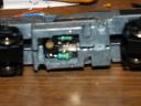
the motor contacts. A capacitor was attached to each motor contact and then back to the metal casing around the motor. Another capacitor was attached across the motor contacts. The resistors were attached between the power wire and the motor contact. The picture shows the underside after cutting off the capacitors.

I wondered if these might be causing the noise and performance problem. I figured the resistors were okay, just holding back some power to the motor, but I cut off all the capacitors, being careful not to cut the power lead. There was no difference when I ran the loco. So I went on to decoder installation.

After removing the body I saw that the decoder was a long one and that the LED’s were soldered directly to the board. I would have to figure out some way to mount the LED’s after I installed the D13SR decoder. As I was pondering that I noticed the decoder was screwed to the frame at each end just behind the LED’s. Then I thought that since this decoder was crap anyway why bother trying to save it? So, I used my razor saw to cut the decoder just behind each LED and screw. The old circuit board became the LED mount.

Next I unsoldered the wires from the now dead decoder. Double sided tape held the new decoder securely on the frame. I positioned it so that the wired end was roughly centered in the loco. I figured I could use the existing wires to do the whole install, including wiring the LED’s.

Bachmann used orange and purple wires to the motor (the standard is orange and grey). I figured I’d use the purple wire for grey and see how it worked out. I unsoldered the orange and grey wires from the decoder and soldered the motor leads in their place.

I trimmed the red and black wires to reach the nearest pickup leads and used the bit I trimmed off to run back to the other pickup leads. I made sure I put the shrink tubing on before I soldered everything together.

I trimmed the blue wire so that the 1000 Ohm resistor (as per the decoder’s instructions for use with LED’s) would reach to the nearest LED. The length of blue wire I trimmed off almost reached the other LED so I had to scrounge for another wire to run from one LED to the other.

I wasn’t sure which lead of the LED was the anode or cathode side so I had to wing it. I soldered the resistor to one side of the nearest LED and joined this to the same side of the other LED. Then I soldered the yellow wire to the other lead of the rear LED and the white wire to the other lead of the front LED.

bachmanndecoder-1.jpg

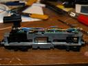
This is the loco with the D13SR installed.

Then came the moment of truth. You should always test a new install by putting the loco on the programming track and attempt to read a CV. If that works without an error then you have no shorts. Once I knew the decoder was installed properly I put the loco on the main line and checked operation.

Wow! There wasn’t a sound as the loco moved down the track! But I had the leads on the LED’s reversed so the lights didn’t work. Back to the bench to switch the leads and back to the main line. The lights worked and the engine ran like a top.

The second loco took half the time and I didn’t mess up the LED’s. It also had a bit of a motor growl, but neither had the same power hum that they had before.

Brian called then with a computer problem that I was going over to help him with. I mentioned the locos and he asked me to bring one over so he could see it run. He was totally amazed at the difference. He had an Athearn CN GP35 shell that we determined would fit on the Bachmann frame with a little modification. So, off to Menzells’ to pick up another of the CP units he had so Brian could install a D13SR into and fit his CN shell on. I’ll get pictures of his unit when we operate there in a couple weeks.

op-141.jpgI decided that they ran so well they were worthy of being weathered. Here they are waiting to go to the service tracks in Tidewater during a recent operating session on the BS&T. Two very nice running locos with new decoders for about $50 each.

Later!

Scott

Trees. More Trees!!!!!!

Well, sticking with my resolution to have trees for my UMG modules at the Truro Train Show in October I have been fairly busy. I’ve spent quite a few evenings since MudFest making trees while watching TV.

Two groupings of future trees.

I use natural materials for tree forms. The trees in the background are made using the dried flowers of False Spirea. I harvest these during the winter when the old seed pods are very dry and crumble off the stem easily. The trees in the foreground use a type of plant that I don’t think we’ve identified yet. They grow in, amoung other places I’m sure, the field behind Jon Huneault’s house in Aylesford, N.S. They have lots of fine branches and look like a very bushy tree.In either case, I use Woodland Scenics Polyfiber for fine branches. Pull a small amount of the polyfiber off the bunch and roll it into a tight ball. Then start pulling it out, teasing it, until you have a very light and airy puffball. It should be teased out fine enough that you could lose it if you dropped it on the floor. I make a bunch of these, some small and some large for variations of branch sizes before moving on to the next step.

I put a fine coating of white glue on the branches that I will be attaching the polyfiber puff balls to. Then I either skewer the puffball with the branch or drape it over the branch. You can leave some branches leafless to simulate dead branches.

Remember the leaves of some real trees do not go around a branch in a perfect circle. You should also remember that not all trees are perfect globular forms. Real trees can have branches sticking out at odd angles and have clumps of leaves outside the main canopy of the tree.

The final step is to apply the leaves. I used to use cheap hairspray as adhesive to attach leaf material. It’s fine for trees that get planted on a home layout and never get moved, but trees that are transported for a portable layout need something more. Lately I’ve been using clear, mat wood finish (Varathane). It’s a little more expensive than hairspray, but I think it will hold up better.

I use different leaf material depending on the type of tree I’m attempting to replicate. I use regular ground foam for smaller bush type trees – ones that typically have smaller leaves. For larger trees I use a product I discovered a couple years ago by accident – leaves from Selkirk Scenery. If you’ve never visited Bill’s site before you should check out his “How To” links. He makes some incredible scenery!

A tree made with Selkirk Scenery
leaves and False Spirea stem.

Anyway, spread out some newspaper to protect the floor from the adhesive and to catch excess leaf material for re-use. It’s a good idea to have two areas of newspaper, one for spraying and one for excess leaf material. I start by spraying the underside of the tree and sprinkling a darker shade of leaf material over it, from the bottom up. This will simulate leaves shaded by the upper branches. Shake off the excess leaf material and spray another coat of adhesive to secure the leaves. Now, spray adhesive from the top down and sprinkle on a lighter shade of leaf material. Shake off the excess and spray another coat of adhesive.

Once the adhesive dries the tree is ready to plant.

It may take a few trees to get the knack of which colors work best for your layout, and your lighting conditions. Before you know it you’ll have a whole forest of trees on your layout.
I’ll have more on making trees in future posts.

Have fun making and planting trees!!!

Scott

Better Late Than Never

I know it has been more than a week since my last update. I’m sorry, okay!? Life has been a little busy lately.

I finally got to the basement on Saturday and spent about 6 hours there. I went down with the intention of working on cars – checking weight. wheel gauge, couplers, etc. – but saw all the stuff not unpacked from the Moncton train show. So, I went about doing that and saw half a box of trees that I hadn’t unpacked and thought I’d put those in Stevenville. Well, I figured Stevenville needed a little scenery work before I planted the trees. Four hours later I still had not worked on any cars but part of Stevenville had grass, there’s a bit of a weedy mess around the tenement, and the main line tracks through town are ballasted.

Then I decided I’d install a bolt alignment system for my main lift-out. I needed something very long in order to be able to adjust them through the benchwork. So, off to Canadian Tire to pick up a couple 8″ eye bolts and nuts. The nut is countersunk and epoxied into the main support for the lift out (centered side-side and front-back). The eye bolt goes up from the bottom of the benchwork into the nut. A few turns and no more shims needed. Works like a charm! So far I haven’t had any horizontal alignment problems. The notch for the lift-out is a very snug fit from side to side.

Since I’m in the tip giving mood, here’s a floor covering solution I found. Tired of sore feet and legs from standing for long periods in a room with concrete floors? I got these inexpensive anti-fatigue mats ($10 for 4 sq. ft.) at WalMart, but I’m sure other stores carry them as well. You really notice the difference when you walk form these onto bare concrete.

Sunday was spent doing an actual cleanup in preparation for the operating session that evening. I took 2 shopping bags of compostables and 3 bags of waste out to the cans! After 4 hours of work the train room sure looked tidier than it had! The next cleaning project will be the staging room/dispatcher’s office/storage room/paint room/… (and it’s only 6′ x 8′)!

I hope I have redeemed myself with this post. Happy modelling!

Scott