JMRI Clinic for MFMR Convention 2011

Here are some links for more information in followup to the clinic I gave at the MFMR Convention on May 14, 2011.

JMRI is a very useful tool for anyone using Digital Command Control.  In it’s basic use JMRI – DecoderPro is a godsend for programming DCC mobile decoders.  I really don’t know how folks not using DecoderPro get along.  I have one loco Proto RS-11 with QSI sound that “loses it’s mind” every now and then during an operating session.  Since I have the settings for all my locos stored in my DecoderPro roster file it takes only a minute or two to set the loco back to my customs settings and it’s back in operation on the layout.

Since the introduction of WiThrottle – a server and application combination – there has been a revolution in wireless throttle technology.  Now we use our iPhones, iPods, and Android phones as throttles when we operate.  The great thing about it is that our throttles are now universal – they will work on any DCC system as long as it has a computer interface, DecoderPro, and a wireless home network.

Anyway, on to the “more information” part of this post.

JMRI web sitehttp://jmri.sourceforge.net/

At the moment 2.10 is the stable production version.  2.11.4 is the current test version.  In my experience it is relatively safe to install the test versions to take advantage of new features, but beware that there may be issues.  If you do have problems with a test version you can always reinstall the previous version.

DecoderPro Manualhttp://jmri.sourceforge.net/help/en/manual/index.shtml

With the rapid development of JMRI this manual is almost always out of date.  But it would certainly help for basic/older features.

JMRI Yahoo Grouphttp://groups.yahoo.com/group/jmriusers/

A great resource when you are really stuck.  The developers of JMRI check the group daily – some several times a day.  If you ever have a problem or question this would be the first place to ask your question.

Other JMRI Clinicshttp://www.rr-cirkits.com/Clinics/Clinics.html

A collection of other presentations on most aspects of JMRI.  If you are into automation, dispatching, or remote control this is a great resource.

JMRI on YouTubehttp://www.youtube.com/results?search_query=jmri

Lots of great (and some not so great) videos about how folks are using JMRI – from the basic to advanced.

My PresentationClick here

Probably not as good as many of the other presentation you’ll find on the internet, but it does have some links to neat videos of JMRI in use.

BS&T – Live and Plugged In!

As you may already know, I use a Lenz system for locomotive control. Because we mostly use XPA’s and cordless phones for throttles I have not added a throttle bus to the layout, except for a single plug at each yard.

The only reason I had those throttle plugs was for Brian. Before he got his XPA he preferred his LH-90. He also liked working the yards so I installed plugs in the yards so he could work them. He’s gotten to like using a cordless phone after getting his own XPA and, heaven help us, he’s running around the layout more! Watch out!

Over the Christmas holidays my son and his friends wanted to try running trains – the first time they’ve shown any interest. Without the throttles the regulars bring on op nights I needed more throttles. I have an LH-90, but without throttle plugs around the room it was not very useful. So I borrowed Brian’s XPA for a few days. The boys had a great time. My son said he didn’t think it would be as much fun, or as difficult, as it was. They didn’t finish the session the first night so the next day one of my son’s friends asked when he could “complete his mission”. Too much “Call of Duty” for those boys, I think.

Anyway, that got me on the kick of installing throttle plugs around the room for those times when we need to use the old standby throttles. The local dollar stores didn’t have any telephone wall plates, but had lots of telephone extension cables, so $5 later I had all the wire I would need.

plugs-1.jpgI found some nice double outlet wall plates at Canadian tire that would be perfect for about $6 each,. I visited a discount store in Quebec City to browse and found some 5-way telephone connectors. I haven’t seen these in stores in a while so I got 4 at $1.50 each. I knew they’d come in handy for something.

The white wall plates would not match my black fascia so the first thing I did was to remove the wiring part from the back of the plate so I could spray them black .

wiring-2.jpgWhile the paint was drying I installed a couple of the 5-ways under the layout in strategic locations. One was close to where the main throttle bus line comes from the command station so I could connect into it. I ran extension cables to the other 5-way to make it “live”. Then ran extension cables from those to where I’d install the wall plates.

I cut the extension cables so that I would get two runs of cable from each 5-way to the wall plates. The cut ends were used at the screw terminals of the wall plates. Fortunately, I only had one run where the remaining cable was not long enough for another run. Each plug on the wall plate was separate so I had to wire them together and used the excess cable for this purpose.

Regular telephone extension cable (the ones with male plugs on each end) are not wired properly to be useful for XPressNet (Lenz’s wiring scheme). The plugs on each end are wired opposite to one another (twisted), while Lenz’s scheme requires both plugs to be wired the same (straight). So when it came time to connect the wire to the plugs one length of the extension cable would be attached color for color (black, red, green, yellow) and the other section would be the reverse (black to yellow, red to green, green to red, and yellow to black). I had to experiment to see which way the wires went before making anything to permanent. One way the LH-90 would work, the other it wouldn’t. It seems you can’t damage anything with incorrect wiring – Yay!

plugs-2.jpgI ran into a problem in Kenville. There is a 1″x3″ behind the 5-1/2″ fascia that I didn’t want to cut into to install the plugs. I visited the only other dollar store in town that I hadn’t been to previously and found some telephone wall plugs with a rectangular inset plug. I cut some neat holes in the fascia, below the 1″x3″, just the right size and epoxied the inset portion into the opening. I just have to paint around the edges to blend them in. That will get done before operating on Sunday.

Later!

Scott

Decoder Identification – part deux

Well from the responses I’ve had it could be either an NCE N103 or a Lenz LE103. I have not been able to find many images of the decoders, but from the descriptions I’ve found they don’t sound like the one I have. I believe that both have a rear light function (yellow wire) which mine does not.

Now, Don Parnell pondered that perhaps the yellow wire got broken off at some point before the installation so the installer just connected the rear light to the green function wire. I’ll look a little more closely at the decoder later to see if there’s a conspicuous solder tab missing a wire.

One thing that seems odd is that DecoderPro identifies it as an NCE decode, yet I was told it was a Lenz decoder when I bought it, and a Lenz decoder was one of the suggestions. Could DecoderPro make such a big mistake with the decoder family?

Thanks for the help to this point folks!

Scott

Decoder identification help, please

Does anyone know what decoder this is? DecoderPro identifies it only as an NCE decoder, but nothing more than that. I can’t find one on the NCE site that quite looks like it.

w-p1125912.jpg

It is about 1″ inch long by about 3/8″ wide.  It only has one headlight function, white wire, and two other functions (green and purple wires), but no yellow for rear light.  I want to see if I can reconfigure the green function to work like a rear light for directional lighting.

I’ll likely just end up replacing the decoder to get proper light functions.

I appreciate the help.

Scott

Addendum to Improving a Bachmann DCC Equipped GP35

Apparently NCE has a replacement board designed for this locomotive. The Bach DSL decoder will fit in place of the old decoder and apprently includes LED’s.

Bach DSL Decoder from NCE

And they are quite affordable too. A quick search indicated prices ranged from $15 to $20 US. I wish I had thought to look for these a few weeks ago. Oh well, the D13SR’s work fine.

Scott

Improving a Bachmann DCC-Equipped GP35

I bought a couple of these locomotives about a year ago from our local model railroad supplier. I needed some extra power on the BS&T and because they were real cheap (<$40). I figured I couldn’t go wrong at that price!

Well, they ran “ok”, but had poor slow speed performance and hummed very loudly. You know the decoder hum you get from some cheap decoders? What did I expect for $40?

A couple months ago I bought a few NCE D13SR decoders for various locos I had without decoders. I planned to try them in these locos to see if it would make much difference. Well, I finally got around to that last week – while Kim was off to the states taking advantage of the high Canadian Dollar.

When I removed the fuel tank covering the body mount screws I was surprised to see a mess of capacitors and resistors attached to bachmanndecoder-2.jpgthe motor contacts. A capacitor was attached to each motor contact and then back to the metal casing around the motor. Another capacitor was attached across the motor contacts. The resistors were attached between the power wire and the motor contact. The picture shows the underside after cutting off the capacitors.

I wondered if these might be causing the noise and performance problem. I figured the resistors were okay, just holding back some power to the motor, but I cut off all the capacitors, being careful not to cut the power lead. There was no difference when I ran the loco. So I went on to decoder installation.

After removing the body I saw that the decoder was a long one and that the LED’s were soldered directly to the board. I would have to figure out some way to mount the LED’s after I installed the D13SR decoder. As I was pondering that I noticed the decoder was screwed to the frame at each end just behind the LED’s. Then I thought that since this decoder was crap anyway why bother trying to save it? So, I used my razor saw to cut the decoder just behind each LED and screw. The old circuit board became the LED mount.

Next I unsoldered the wires from the now dead decoder. Double sided tape held the new decoder securely on the frame. I positioned it so that the wired end was roughly centered in the loco. I figured I could use the existing wires to do the whole install, including wiring the LED’s.

Bachmann used orange and purple wires to the motor (the standard is orange and grey). I figured I’d use the purple wire for grey and see how it worked out. I unsoldered the orange and grey wires from the decoder and soldered the motor leads in their place.

I trimmed the red and black wires to reach the nearest pickup leads and used the bit I trimmed off to run back to the other pickup leads. I made sure I put the shrink tubing on before I soldered everything together.

I trimmed the blue wire so that the 1000 Ohm resistor (as per the decoder’s instructions for use with LED’s) would reach to the nearest LED. The length of blue wire I trimmed off almost reached the other LED so I had to scrounge for another wire to run from one LED to the other.

I wasn’t sure which lead of the LED was the anode or cathode side so I had to wing it. I soldered the resistor to one side of the nearest LED and joined this to the same side of the other LED. Then I soldered the yellow wire to the other lead of the rear LED and the white wire to the other lead of the front LED.

bachmanndecoder-1.jpg

This is the loco with the D13SR installed.

Then came the moment of truth. You should always test a new install by putting the loco on the programming track and attempt to read a CV. If that works without an error then you have no shorts. Once I knew the decoder was installed properly I put the loco on the main line and checked operation.

Wow! There wasn’t a sound as the loco moved down the track! But I had the leads on the LED’s reversed so the lights didn’t work. Back to the bench to switch the leads and back to the main line. The lights worked and the engine ran like a top.

The second loco took half the time and I didn’t mess up the LED’s. It also had a bit of a motor growl, but neither had the same power hum that they had before.

Brian called then with a computer problem that I was going over to help him with. I mentioned the locos and he asked me to bring one over so he could see it run. He was totally amazed at the difference. He had an Athearn CN GP35 shell that we determined would fit on the Bachmann frame with a little modification. So, off to Menzells’ to pick up another of the CP units he had so Brian could install a D13SR into and fit his CN shell on. I’ll get pictures of his unit when we operate there in a couple weeks.

op-141.jpgI decided that they ran so well they were worthy of being weathered. Here they are waiting to go to the service tracks in Tidewater during a recent operating session on the BS&T. Two very nice running locos with new decoders for about $50 each.

Later!

Scott

Commentary on DCC

The goals of the UMG (Un-Named Modular Group) are to promote the hobby of model railroading and to expose people to the operations side of the hobby. Some would argue the primary goal is to have a good time with a bunch of great guys, but that’s actually just a bonus.

One of the things that we encourage our “members” to do at public shows is to talk to visitors and explain what we do, why we do it, and how we do it, even at the expense of blocking the main line. During shows we have to have a “sweeper operator” go around the layout and move trains abandoned by operators engaged in deep conversation with a visitor.

One of the most common topics we get asked about is DCC. The amount of misinformation that is available on the web, and supposed “common knowledge” of non-DCC modelers, is astounding.

I’ve discovered a few sites lately with a lot of great information about DCC that I’d like to share. They shed some light on the myths and misinformation.

Joe Daddy has a lot of great information about Model Railroading Urban Legends which covers more than just DCC. His Legend #5 is one that always gets me – “Use the biggest wire for your DCC bus that you can, preferably 12 gauge twisted.”

First, have you ever tried to twist 12Ga. wire? Second, why would you need heavier wire for your layout than what’s used to carry power throughout your house? Most home wiring uses 14Ga. wire to carry 110 volts at 15amps! Most DCC layout wiring carries 15 – 20 volts at 5amps.

The pundits of heavy wire state that there is less resistance in the larger wire resulting in less power loss. Some hunting on the web shows that 16Ga. copper wire will lose about 6.5v over 100m (328ft.), while 14Ga will lose about 4v in the same distance (at 5 amps). This would be a problem on some very large layouts but not so much for the average home layout. If voltage loss is a concern you should place the command station/booster in the middle of the section it is powering to reduce the wire run as much as possible. If your runs are really long, adding boosters to the middle of power blocks will help.

I used 16Ga stranded wire. Apparently, stranded wire should have less power loss because electricity runs on the surface of the wire. So, more wires equals more surface area equals less power loss.

Steve Jones has several pages dedicated to DCC Myths on his blog – Electric Nose. The one that irks me the most is the issue of DCC Friendly Turnouts (being in the UK Steve calls them “points”). Some websites scare modelers away from DCC by telling them they need to make a tons of modifications to their turnouts before they can run DCC. Steve points out that it is not a problem of DCC, it is more often a problem of wheels, or the turnout, being out of gauge.

I’ve built two DCC layouts of my own, and helped friends with several more. We have never had to do anything more than insulating the frog rails on power routing turnouts to avoid shorts. Well, there were a few used turnouts that we had to set the gauge of the point rails and some that we had to shim the guardrail, but those were more of a derailment issue than a shorting issue.

DCC command stations are much more efficient at detecting shorts than DC systems are. When trains are run on a DC layout there may be shorts happening all over the layout, but neither you nor the DC controller notice them so the trains keep rolling along. DCC systems are very sensitive to shorts since the power output (5 to 10 amps) is generally much higher than DC systems. They shut down at the first sign of a short to protect the layout. So a layout that seemingly runs fine on DC may not run quite so fine on DCC. But that not a problem of DCC, it’s a layout problem and is rarely very difficult to fix.

You’ll see a lot of layouts on the web that have what looks like very complicated wiring. Some people will think that’s because they use DCC. On those layouts DCC is only a small part of all the wiring. Items like electric turnout controls, signal systems, occupancy detection, and scenic lighting all add to the wires running under a layout. You shouldn’t just look at a picture of complex wiring and think “DCC”. Read the text and see what else they’ve got going on their layout. Remember, DC layouts can have much more complex wiring than DCC layouts due to multiple throttles and power blocks.

Railroadman, Daryl Dankwardt, has a great post about complex wiring – Don’t be Intimidated by all the Wiring – that shows photos of his wiring. It looks complex, but he uses DC and is doing a lot with all those wires. He has electric switch machines and has a control/dispatcher’s panel with LED indicators, turnout controls, and throttle selection switches. His wiring is very neat, especially when compared to some other layouts I’ve seen.

Scott

Shield’s Up!

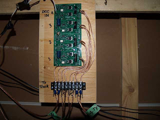
So, I finally installed my Power Shield (PS4) from Tony’s Trains a few weeks ago. I installed the thing the afternoon of an operating session on the BS&T. I only had time to install two zones. But it was enough to make a difference during the session.

The feature that really bugs me about using Lenz DCC is the way it handles shorts. Having to press a button to recover from a short is a pain. What usually happens is that more than one person presses the button – the first guy turns the layout back on, the second guy turns it off again. Now you wonder if the short cleared up? So everyone fiddles with their locos and the whole process starts again with a couple guys pressing buttons. You’d think we’d learn to assign an “official button presser”. Nope.

Anyway, we only had a few shorts during the next session (there’s still a few turnouts in need of repair), but we didn’t have to press any buttons. The PS4 reset automatically after the short was cleared.

I installed the other two power zones on the afternoon of the last operating session. It seems an op session provides an incentive to get something done on the layout. It’s great! Now only 1/4 of the layout is affected when a short occurs.


Both yards at Bayside and Tidewater are on separate zones, as are Stevenville/Derwin’s Drop and Chappellton/Kenville.

The next project for the PS4 is to install short indicator lights around the layout. I think this is something that can be done, but not exactly sure yet how to do it.

I know, it’ll be even better once I get the source of the shorting problems repaired. That’s a project for another day(s).

Scott